
 Domestic hot water circulation systems compensate for heat loss from piping segments by facilitating continuous flow through a heat source to maintain water temperatures throughout the system. To ensure that piping segments receive flow proportional to the heat loss imposed on the system, a balancing valve is provided at each circuit for flow regulation (see Figure 1). A circulation system with properly balanced circuits regulates flow to maintain a uniform temperature at each balancing valve. Proper balancing of domestic hot water circuits is often overlooked or substituted with approximate methods by design-engineers and installers, leading to significant inaccuracies. ASHRAE Standard 188 and Guideline 12 have emphasized the necessity of designing and installing a properly balanced system, with the objective of maintaining domestic hot water temperatures above the growth range of Legionella throughout the circulation piping. Designing a properly balanced system will also allow for smaller-diameter return piping, translating to reduced installation costs and reduced heat loss. The Product Ratio Method offers a solution to determining circuit flow rates using a set of equations, allowing the flow through the balancing valve to be determined during the design phase of the system.

Development
Methodologies for calculating balancing valve flow rates have been developed and published in a number of engineering guidelines and standards, including the Plumbing Engineering Design Handbook published by ASPE, the Design Manual for Water Supply and Drainage Systems published by China Architecture Design & Research Group, and DIN 1988-300 published by the German Institute for Standardisation. All three approaches are similar, with the main difference being that the method from the Plumbing Engineering Design Handbook catalogs piping segments using taxonomical designations whereas the other methods use sequential numbering designations. The Product Ratio Method, first introduced in the 2013 edition of the Plumbing Engineering Design Handbook, establishes relationships between segments using taxonomical designations. When designations and the associated heat losses are tabulated, downstream segments may be isolated from upstream segments using the designations, allowing calculations to be made without referencing a diagram.
Circuits and Balancing Valves
A circuit is defined as the supply and return piping facilitating a circular path of flow through the heat source, such as a water heater or heat exchanger. Systems with multiple circuits have some piping segments shared between other circuits, assisting in the flow distribution for heat loss recovery. Circulation systems and circuits are designed for conditions where there is no demand for hot water at plumbing fixtures and all flow in the system is facilitated by the circulation pump. During periods of demand for hot water, the temperature drop through the supply system will be lower. Balancing valves regulate the flow of circuits by increasing or decreasing the friction loss through the circuit, allowing the system to be configured so that circuits with the least friction loss, such as the circuits closest to the water heater, do not receive a disproportionate amount of flow compared to circuits with greater friction loss, such as those furthest from the water heater. An unbalanced circuit is a circuit that receives either insufficient flow or excessive flow. Insufficient flow through a circuit will result in water temperatures falling below the design conditions. Excessive flow through a circuit will require larger return piping diameters, leading to greater heat loss and energy consumption. If flow is underestimated when selecting return piping diameters, high velocities may compromise the integrity of the piping and result in material failures. The system flow, equivalent to the circulation pump flow, should account for the heat loss of the return piping to ensure that the temperatures are maintained above 120°F (49°C), in accordance with ASHRAE Guideline 12-2020. Further guidance on determining the system flow and selecting distribution and return temperatures is covered in Maintaining Domestic Hot Water Return Temperatures Above the Growth Range of Legionella, published by ASPE.
While there are many different types of balancing valves, balancing valves can be generalized into two categories: flow calibration or temperature calibration. The temperature-calibrated type dynamically regulates flow to maintain the temperature setpoint at the valve. The flow-calibrated type regulates flow depending on the flow setpoints and is dependent on proper calibration to produce a uniform temperature at each valve. While the temperature-calibrated type dynamically maintains a uniform temperature at the balancing valves, design calculations are still necessary for the selection of return piping diameters and temperature analysis in the return piping. Flow-calibrated types include manual balancing valves and pressure-independent control valves, while temperature-calibrated types include thermostatic balancing valves and electronically actuated balancing valves.
Taxonomical Designations

A segment is defined as a stretch of piping with each end terminating in a node (i.e., branch tee) or an endpoint, such as a balancing valve or water heater. To analyze the heat loss and determine the flow rate for each piping segment, all segments must be assigned a unique designation. Segment and node designations consist of 𝑎 and 𝑏 characters, except for the first segment and node. The first segment, between the heat source and the first node, is assigned the designation 0. 100 percent of the circulation system flow passes through segment 0 before branching off to other segments, with flow being divided according to the heat loss of downstream segments. The two segments downstream of the first node (Node 0) are assigned the designations 𝑎 and 𝑏 (see Figure 2).
For reproducibility of calculations, the designation should be reserved for the segment assumed to have the lowest downstream heat loss. Downstream segment designations carry over the designation of the upstream segment in the designation prefix, adding another 𝑎 or 𝑏 following the second node as the suffix. The same process is repeated until all segments have been assigned designations. An example of a domestic hot water circulation supply segment diagram is shown in Figure 3. To improve readability for designations with many characters, designations may be broken into groups of five characters, separated by a hyphen and a grouping number.

Heat Loss (Φn, ΦΣn)
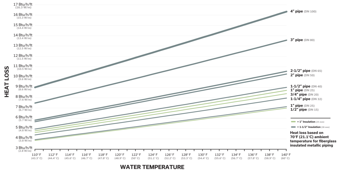
When calculating circuit flows, the heat loss values are taken from the circulated portions of the domestic hot water supply system. Because the heat loss associated with the return piping is downstream of the balancing valves, return piping is excluded from the circuit flow heat loss calculations. The heat loss from each segment (Φn) should be tabulated and used to calculate the heat loss at each node for all downstream segments (ΣΦn). Heat loss per unit length values vary depending on the pipe type and diameter, insulation type and thickness, water temperature, and ambient air temperature (see Figure 4). Heat loss calculations first require the selection of supply piping diameters and insulation thickness for each segment. For example, a 50 foot (15 m) segment with a heat loss per unit length of 7 Btu/h/ft (6.7 W/m) has a heat loss of 350 Btu/h (103 W). When calculating heat loss from circuits, the balancing valve acts as the delineation point between the supply and return piping. The ΣΦn values represent the heat loss of a given segment and all segments downstream. The example in Table 1 indicates that ΣΦbba has a heat loss of 510 Btu/h (140 W).
Node Ratio (rn)
The node ratio defines the proportion of flow passing into one of the two downstream segments of a node. Taking the ΣΦn values from the a and b outlets of a node and inserting them into Equation 1 produces the ratio of flow to be directed through each segment.

In the example below, the ΣΦn values from Table 1 are used with Equation 1b to calculate the rn value for segment bb. The rbb value indicates that 73 percent of the flow passing through node b is directed into segment bb, leaving segment ba with the remaining 27 percent.

Product Ratio (Rn)
The product ratio value reflects the proportion of total system flow passing through a segment. The Rn value of a segment is equal to the product of all upstream rn values. Rn values should be tabulated for each segment (Table 1). The procedure for calculating the Rn value in the example for segment bba is as follows:
![]()
Segment Flow (qn)
Rn values are used in combination with the system flow (qs) to calculate the flow through each segment (qn), allowing for the flow at each balancing valve to be determined (Equation 2). A qs value of 3.0 gallons per minute (gpm) (0.19 L/s) is used in Table 1 to allow for the selection of qn values.1 Using the Rbba value from Table 1 of 0.22 and a qs value of 3.0 gpm (0.19 L/s) in Equation 3, the calculated flow for segment bba is 0.7 gpm (0.04 L/s).


Temperature Analysis
If flow-calibrated type balancing valves are used, limited precision may result in qn values that differ from the calculated qn values, producing a less uniform temperature in the balancing valves. Equation 3 is used to assess the temperature drop across a segment (Tn) with different qn values to ensure that the system will operate within the design temperature range. Equation 3 may also be useful for verifying the accuracy of circuit flow calculations. Computer applications, such as spreadsheets, may be configured to populate rn, Rn, and qn values using Φn values with the associated segment designations and the system flow, simplifying the calculation process and reducing the risk of errors.

Summary
The Product Ratio Method provides an approach for determining the flow rates of domestic hot water circuits during the design-phase. Circuit flow calculations are necessary for the selection of return piping diameters and ensuring temperatures in the piping do not fall below design conditions. Inaccurate assumptions frequently fail to meet the Legionella mitigation protocols outlined in ASHRAE Standard 188 and Guideline 12 and pose a public health risk. Additionally, improperly designed circuits may produce unnecessary energy consumption as a result of high circulation pump flow and larger return piping diameters. A domestic hot water circulation system with properly balanced circuits will produce a high-performance circulation system that prioritizes both public health and energy efficiency.
1Guidance on determining can be found in Maintaining Domestic Hot Water Return Temperatures Above the Growth Range of Legionella
Resources
Plumbing Engineering Design Handbook, Volume 2 (2018), American Society of Plumbing Engineers
Lansing, J. (2019), Maintaining Domestic Hot Water Return Temperatures Above the Growth Range of Legionella, American Society of Plumbing Engineers
Design Manual for Building Water Supply and Drainage (2019), China Architecture Design & Building Press
DIN 1988-300: Drinking water supply systems: Pipe sizing; DVGW code of practice (2012)
Guideline 12-2020: Managing the Risk of Legionellosis Associated with Building Water Systems (2020), American Society of Heating, Refrigerating, and Air-Conditioning Engineers
Standard 188-2018: Legionellosis: Risk Management for Building Water Systems (2018), American Society of Heating, Refrigerating, and Air-Conditioning Engineers
About the Author
 John Lansing, CPD, LEED Green Associate, is a Certified Plumbing Designer in Portland, Oregon, working with PAE Consulting Engineers. John was the recipient of the World Plumbing Council’s 2018 Education and Training Scholarship, which gave him the opportunity to author a report on differences between British and American plumbing engineering. He also authored Maintaining Domestic Hot Water Return Temperatures Above the Growth Range of Legionella, published by ASPE. John is passionate about sustainable and regenerative plumbing strategies as well as studying plumbing engineering standards and design guides from other countries. To connect with John with questions or comments, please visit his LinkedIn profile.
Any opinions expressed in this article are those of the author and not the American Society of Plumbing Engineers.


